Plastic Manufacturing Guide
Manufacturing Process of Plastic Injection Moulding: Process Steps, Materials and Quality Checks
A clear breakdown of the plastic injection molding process, covering each step from clamping to ejection, key machine parameters, material behavior, common defects, tooling cons...
What Is the Plastic Injection Molding Process?
Plastic injection molding is a manufacturing process that produces identical plastic parts in high volumes by injecting molten material into a precisely shaped mold cavity. The cycle repeats rapidly, making it the dominant method for mass-produced plastic components in industries like automotive, medical devices, consumer goods, and electronics. The core principle is straightforward: melt plastic granules, force the melt into a closed mold under pressure, cool until solid, then eject the finished part. However, the quality and consistency of the final product depend on tight control of temperature, pressure, flow, and cooling across hundreds or thousands of cycles.
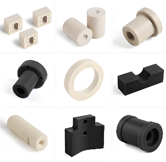
Step-by-Step Plastic Injection Molding Process
The injection molding cycle can be broken into five main stages. Each stage must be optimized for the specific material, part geometry, and production requirements.
1. Clamping
The mold halves are securely closed and held together by the clamping unit. The required clamping force depends on the projected area of the part and the injection pressure. Insufficient clamping force may allow the mold to open slightly, causing flash along the parting line.
2. Injection
Plastic pellets are fed from the hopper into a heated barrel. A rotating screw melts and homogenizes the material. Once enough melt is ready, the screw acts as a plunger, injecting the molten plastic at high pressure through the nozzle and into the mold cavity. Key parameters during injection include melt temperature, injection speed, and injection pressure. According to the Injection Molding Handbook (Osswald, Turng & Gramann, 2nd Edition, Chapter 4), maintaining a uniform melt temperature and consistent screw recovery time is critical for shot-to-shot consistency.
3. Dwelling (Pack and Hold)
After the cavity is filled, additional material is pushed in under holding pressure to compensate for shrinkage as the plastic cools. The gate freezes only after the holding phase ends. Inadequate packing can cause sink marks, voids, or dimensional instability.
4. Cooling
The part continues to cool inside the mold until it is rigid enough to be ejected without deformation. Cooling time often accounts for 50% to 80% of the total cycle. Uniform cooling is essential to prevent warpage and to maintain tight tolerances. Cooling channel design in the mold plays a decisive role.
5. Mold Opening and Ejection
The clamp opens, and ejector pins or a stripper plate push the part out of the cavity. Rapid, clean ejection helps minimize cycle time and prevents part damage. The mold then closes, and the cycle repeats.
Key Machine Controls and Parameters
Precision in injection molding relies on four primary process variables. Monitoring and controlling these parameters directly affects part quality and repeatability.
| Parameter | Function | Common Measurement |
|---|---|---|
| Melt Temperature | Affects flowability, degradation risk, and surface finish. | Measured at the nozzle tip, typically in °F or °C. |
| Injection Pressure | Determines how quickly the cavity fills; must overcome flow resistance. | Hydraulic or specific pressure, often in psi or MPa. |
| Holding Pressure | Packs additional material to reduce shrinkage after filling. | Usually lower than injection pressure, set as a percentage or fixed value. |
| Back Pressure | Resistance met by the screw during recovery; improves mixing and melt homogeneity. | Low to moderate values, adjusted based on material and color mixing needs. |
Cycle time is another overarching metric. Although not a direct machine setting, it is affected by all stages and is a key economic factor. Reducing cooling time by a few seconds, for example, can significantly increase output without sacrificing quality if molded-in stresses are managed.
Plastic Material Behavior During Injection Molding
Different thermoplastics behave differently when heated and sheared. Understanding rheology helps predict flow patterns, shrinkage, and potential defects.
- Amorphous polymers (e.g., ABS, polycarbonate, polystyrene) soften over a temperature range and typically shrink less uniformly. They have better dimensional stability but may be prone to warping if cooled unevenly.
- Semi-crystalline polymers (e.g., polyethylene, polypropylene, nylon) exhibit a sharp melting point and higher shrinkage due to crystal formation. They often need longer cooling times and larger holding pressure to compensate for volumetric shrinkage.
- Fiber-reinforced grades shrink differently in the flow direction versus transverse direction, causing anisotropic shrinkage. Gate location and orientation are critical.
Moisture content is another critical factor. Many plastics (nylon, PET, PC) are hygroscopic and must be thoroughly dried before processing to prevent hydrolysis and surface defects. Recommended drying times and temperatures are material-specific and should be strictly followed.
Common Defects in Injection Molded Parts and How to Avoid Them
Even well-established processes can produce defective parts when parameters drift or tooling wears. Recognizing typical problems and their root causes helps operators react quickly.
| Defect | Appearance | Likely Causes | Corrective Actions |
|---|---|---|---|
| Sink Marks | Shallow depressions on thick sections or rib roots. | Insufficient packing; cooling too quickly. | Increase hold pressure; extend hold time; reduce melt temperature. |
| Short Shot | Incomplete filling; missing portion of part. | Insufficient material; low injection pressure/speed; flow restriction. | Check material feed; increase injection pressure; raise melt temp. |
| Flash | Thin material squeezes out along parting line or ejector pins. | Low clamping force; worn mold; excessive injection speed. | Increase clamp force; repair mold; reduce injection speed. |
| Warpage | Part bends, twists, or distorts after ejection. | Uneven cooling; excessive molded-in stress; poor gate location. | Uniform cooling; adjust mold temps; optimize hold pressure profile. |
| Burn Marks | Dark or black discoloration, usually near vents or at end of fill. | Trapped air overheating; excessive melt temperature. | Improve venting; reduce injection speed; lower melt temp. |
Regular process audits and using statistical process control (SPC) methods can catch these defects before they become widespread.
Tooling Considerations for Injection Molding
The mold itself is an engineered assembly that must withstand thousands to millions of cycles. Key design elements directly influence part quality and mold longevity.
- Gate type and location: The gate controls how plastic enters the cavity. Edge gates, sub gates, hot tips, and valve gates each suit different applications. Poor gate placement can create weld lines, air traps, or unbalanced filling.
- Runner system: Cold runners waste material but are simpler; hot runners eliminate runner waste but add cost and maintenance. The design must balance pressure drop and solidification timing.
- Cooling channels: Conformal cooling lines follow the part contour for uniform heat extraction. Proper placement reduces cycle time and warpage.
- Venting: Adequate vents (often 0.02–0.05 mm deep) allow air to escape, preventing burn marks and short shots. They must be cleaned regularly.
- Draft angles: A minimum draft angle (often 0.5° to 3°) on vertical walls allows easy ejection without damaging the part or mold surface.
Advanced tool steels and surface treatments (nitriding, chrome plating) extend mold life, especially for abrasive or corrosive materials.
When Injection Molding Works Better Than CNC Machining, Extrusion, or Thermoforming
Choosing the right manufacturing process depends on part complexity, production volume, material selection, and cost targets. The table below highlights typical decision factors.
| Process | Best For | Per-Part Cost at High Volume | Part Complexity | Material Options |
|---|---|---|---|---|
| Injection Molding | High-volume production of intricate, toleranced parts | Very low | High (complex 3D shapes, undercuts possible) | Wide (most thermoplastics, elastomers) |
| CNC Machining | Low to medium volumes; prototypes; very tight tolerances | Moderate to high | High, but limited by tool access | Any machinable plastic or metal |
| Extrusion | Continuous profiles (pipes, sheets, films, profiles) | Low (per foot) | Low (constant cross-section) | Thermoplastics, rubber compounds |
| Thermoforming | Large, thin-walled parts; trays, panels, packaging | Low to moderate | Moderate (formed from sheet, limited detail) | Thermoplastic sheets (ABS, PS, PETG, etc.) |
Injection molding delivers economies of scale unmatched by machining when production runs exceed a few thousand units. However, tooling lead time and upfront mold cost are high. For low volumes or parts that require extremely tight tolerances (closer than ±0.05 mm), CNC machining may be more economical. Extrusion is ideal for continuous lengths with a fixed cross-section, while thermoforming suits simple, large-area components. According to Plastic Part Design for Injection Molding (Malloy, 2nd Edition, Chapter 1), the process should be selected early in the design phase because part geometry, material choice, and tool design are interdependent.
Quality Checks and Inspection Methods
Quality assurance in injection molding combines dimensional verification, visual inspection, and mechanical testing to catch defects before parts reach the customer.
- Dimensional checks: Use coordinate measuring machines (CMM), optical comparators, or manual gauges to verify critical dimensions. Cpk analysis helps monitor process capability.
- Visual inspection: Look for surface defects (sink, flash, short shots, burns, flow lines). Often performed inline or with automated vision systems.
- Mechanical testing: Tensile, impact, or flexural tests on molded specimens validate material properties. These are especially important for safety-critical components.
- Weight checks: Part weight consistency is a fast process indicator; weight variation can signal shorts, flash, or packing inconsistencies.
- Process monitoring: Real-time monitoring of injection pressure, melt temperature, and cushion size with SPC software helps detect drift before defective parts are produced.
A structured first-article inspection (FAI) report is standard practice when a new mold or material is introduced. Long-running production often uses a sampling plan based on ANSI/ASQ Z1.4 or equivalent. Consistent documentation supports traceability and continuous improvement.
Final Takeaway
The manufacturing process of plastic injection moulding is a science-backed cycle of precision, material behavior, and tool design. Mastering the five stages of clamping, injection, dwelling, cooling, and ejection—along with careful control of temperature, pressure, and cooling—lowers defect rates and raises part consistency. Matching the process to the right part volumes and geometries, while understanding how it compares to CNC machining, extrusion, and thermoforming, positions engineers and manufacturers to make sound production choices. Whether you are troubleshooting a current process or planning a new project, attention to tooling details and regular quality checks remains the foundation for reliable injection molding output.
References
Have a related manufacturing question?
Send your drawing, material, quantity, finish and application requirements for a manufacturing review.